Wednesday 29 January 2020

Selection of MCCB for inverter circuit


Causes of distorted waveform current
Distorted waveform current can be caused by CVCF units with thyristors and transistors used as computer power supply units, various rectifiers and VVVF units for induction motor control for meeting the recent trend toward energy conservation. These units are used to make DC power using the semiconductor switching function or further make the target AC power from the DC power. Generally, a large capacitor is connected for smoothing after a rectifier circuit, and, therefore, pulsed charging current to the capacitor flows to the power supply side every half cycle. Load current generated by superposition of high-frequency current by chopped frequency on the fundamental frequency flows to the load side because the voltage is chopped by higher harmonics in the process of conversion to AC power. Below is described the selection for the VVVF inverters which will be developed as the main control method for widely-used induction motors. There are two VVVF inverter control methods, PAM (Pulse Amplitude Modulation) and PWM (Pulse Width Modulation). The harmonic content generated varies depending on the method. To reduce the harmonic content in the input current, according to Tables 5. 18 and 5. 19 , it is effective to add a DC reactor (DCL) or AC reactor (ACL). In the output current waveform shown in Fig. 5. 20, the harmonic content in the case of PWM is higher.


Selection of MCCB
For the power supply side of inverter, at first, select MCCB recommended by the inverter manufacturer. I f the manufacturer does not recommend any MCCB, correct the relationship between MCCB rated current IMCCB and the load current I as shown below in consideration of changes in characteristics and temperature rise due to distortion of load current waveform.


Thermal magnetic (bimetal) and electronic (RMS value detection) type MCCB use current RMS value detecting systems and ensure correct protection against overload even at current with distorted waveform. It is better to select one of these types.


Note (1) Since hydraulic magnetic MCCB may considerably change in characteristics depending on waveform distortion, it is recommended to use thermal magnetic MCCB.


Cases of distorted wave current load and measures
Equipment provided with machines, such as computers, containing DC power supply as loads


Equipment containing thyristor control unit on part of system
In this case, large current distortion is caused at another capacitive branch due to voltage distortion caused in the thyristor control unit.


Tuesday 28 January 2020

Selection of MCCB for capacitor circuit


When selecting MCCB for a capacitor circuit, attention shall be paid to the two points, the circuit opening and closing
points, and harmonic current as stated below.

Leading current circuit opening surge (at circuit opening)
When a capacitor circuit as shown in Fig. 5. 7 is opened at the time t1 shown in Fig. 5. 8, the circuit is broken at the zero point t2 of leading current i. After this, the voltage on the power supply side will change as shown by the Vt curve. However, on the load side, since the voltage is kept at Vc owing to the electrical charge of the capacitor, a potential difference between MCCB contacts will occur as the voltage difference between Vc and Vt, the potential difference will be approx. twice the supply voltage peak value Em at t3 approx. 1/2 cycle after t2, and, if the contacts have not opened sufficiently, reignition of arc will occur. Then, the electrical charge of the capacitor will be discharged by the damped oscillation from the voltage magnitude of 4Em on the oscillation circuit determined by the reactance on the electric circuit and the capacitor capacity. After the arc is extinguished, Vc will be maintained at –Em again, and the potential difference between contacts, the difference between Vc and Vt, will increase. While this is repeated, the contacts will sufficiently open, reignition will not occur, and the circuit will open. Mitsubishi MCCB have extremely high contact opening speed and will rarely repeat reignition. However, note that some MCCB do not have a quick-make/ quick-break mechanism. ON such MCCB, if the capacitor capacity is small, the electrical charge is not discharged until the oscillating current is sufficiently attenuated. Therefore, if the arc is extinguished near the peak value in the reverse direction to the oscillation voltage, the capacitor voltage, as shown in Fig. 5. 9, will be maintained near -3Em at the first reignition and will gradually increase to 5Em at the second ignition and -7Em at the third reignition, thereby leading to damage to the capacitor. Therefore, it is necessary to use MCCB with a quick-make/ quick-break mechanism.


Selection of MCCB in consideration of inrush current (at circuit closing)
When the supply voltage is V (v), capacitor capacity is C (F), frequency is f (Hz) and current is I (A), the relationship with kVA capacity P is determined as shown below.


When the capacitor circuit is closed, the capacitor electrical charge q = CV appropriate to the voltage instantaneous value V in the closing phase must be supplied instantaneously. To supply the electrical charge, large inrush current will flow. Assume that a circuit containing a capacitor has constants as shown in Fig. 5. 10. 1 and the circuit is closed when the voltage V reaches the supply voltage peak value V = Em.


According to the transient phenomenon theory, the flowing current is determined as shown below.


The change in is plotted in Fig. 5. 10. 2, and the maximum value of current im is determined as shown below.


Although the voltage V is not constant, it is allowed to consider V to be equal to Em until the transient phenomenon disappears because t0 is significantly small. Since the transit time is regarded as about 2Ƭ0, for the capacitor circuit, it is necessary to select MCCB having such an magnetic tripping current that MCCB does not operate at the passing current of im × 2Ƭ0.


Then, calculate the time in the following case.
In the case of MCCB for circuit of 3-phase, 200V, 50 Hz, 150 kvar capacitor: According to calculation, C = 1.1943 3 10-2 (F), and I = 433 (A). To estimate R and L of the circuit, the circuit short circuit current is assumed to be approx. 100 times the circuit capacity, 50000A.


Since the transit time is approx. 2t0, select MCCB having an unlatching time of 0.001 s at a current of 6600A. If Model
NF630-SW is selected, since its relay time at 10000A is 0.0029 s, it will not operate at the passing current shown above even if the unlatching time is shorter than this time. However, to prevent abnormal wear or adhesion of MCCB contacts due to large passing current and to ensure the safety against unnecessary operation, the magnetic tripping
current should be set larger than


The rating to ensure that the magnetic tripping current is larger than 4700A is 500A. In Table 5. 14, applicable MCCB rated current values are shown. If the short-circuit capacity of the circuit is remarkably larger than the rated breaking capacity, it is necessary to examine which model to be selected in accordance with the above example of calculation because MCCB may operate not only for protection against short circuit, but also owing to inrush current applied when the circuit is closed. The above selection procedures apply in case where one capacitor bank is used and a reactor is not used. If 1 to 6 capacitor banks and a 6% reactor are used, see Table 5. 14.


  1. The rated current of the circuit breaker to be selected is approx. 150% of the rated current of capacitor.
  2. When capacitor banks are switched according to the change in power factor, separately install electromagnetic contactors to open and close the circuit.
  3. To select the rated current of circuit breaker for main line, determine the sum of the capacitor capacities on the branch circuits, and find the appropriate rated current in the column of the number of banks “1” in the above table.
  4. The values at frequencies of 50 Hz and 60 Hz are shown.
Selection in consideration of harmonic current

 Since capacitors have the property of expanding voltage distortion to several times higher current distortion, if there is a device applying a thyristor which may cause distortion in the voltage waveform near the capacitor, care must be taken in selecting MCCB. It has been reported that the current distortion reached 360% although the voltage distortion was about 19%. If there is a voltage distortion source near the capacitor and the current distortion is large, select a thermal magnetic MCCB for capacitor circuit.


Monday 27 January 2020

Selection of MCCB for primary side of transformer

Magnetizing inrush current of transformer
When power is turn on to a transformer, significantly largemagnetizing current may flow into the transformer. The magnetizing current may have a peak value of 10 times or more the rated current and may cause malfunction of MCCB, and the transformer circuit may not be closed. This current is called magnetizing inrush current. 

The magnetizing inrush current varies depending on at which circuit voltage the transformer has been turned on and in which state the core residual magnetic flux was. The magnetizing inrush current is maximized when the transformer is turned on at point P in Fig. 5. 6. The magnetic flux changes by 2m in 1/2 cycle after the transformer is turned on. Since the magnetic flux starting point is the residual magnetic flux fr in the center of the core before the transformer is turned on, the magnetic flux will be 2m + fr after 1/2 cycle and considerably exceed the saturated magnetic flux of the core, and, as the result of this, large magnetizing current will flow. This magnetizing inrush current attenuates with time. There is a tendency that the higher the transformer capacity, the larger the attenuation time constant. Table 5. 9 shows the approximate values of magnetizing inrush current. The values shown in Table 5. 9 are larger than the actual magnetizing inrush current values because the values were determined not in consideration of current limiting due to electric circuit impedance. If the value is unknown, the value in Table 5. 9 should be used. It is recommended to refer to the transformer manufacturer for details.


Notes 
  1.  Multiple: The first peak value of magnetizing inrush current for rated current peak value.
  2. Since the magnitude of magnetizing inrush current considerably depends on the applied voltage, making phase and residual magnetic flux of core, normally, the magnetizing inrush current changes every time a transformer is turned on. The above table shows the maximum values. Note that the magnetizing inrush current caused when the rated voltage is applied to the rated tap may be larger if overvoltage is applied.

Selection of MCCB for primary side of transformer
The magnetizing inrush current stated in 5. 4. 1 attenuates with time, and, lastly, only the magnetizing current flows. However, the instantaneous trip of MCCB reacts to transient current. Therefore, it is necessary to select MCCB having sufficiently higher instantaneous tripping current than the magnetizing inrush current of transformer. Thermal magnetic MCCB are more suitable than hydraulic magnetic MCCB because thermal magnetic MCCB with high magnetic tripping current can be manufactured easier. Example of selection of MCCB for primary side of 3-phase 420V 50 kVA
The rated current I (RMS value) can be obtained as shown below.


The magnetizing inrush current peak value I is 22 times the rated current peak value.


Accordingly, MCCB having an instantaneous tripping current peak value of 2137A or more should be selected.


select the model which respective to the instantaneous tripping current peak value. 

Follow below instructions to know the instantaneous tripping current peak value of model at 150A.

Therefore this model meet the requirement. 

Sunday 26 January 2020

Selection of MCCB for welder circuit

Selection of rated current of MCCB for spot welder circuit
General spot welders are characterized by intermittent loading with a short period, and the load is switched only on the primary side of the welding transformer as shown in Fig. 5. 3.

Unlike for general circuits, for selection of MCCB for awelder circuit, it is necessary to take into consideration the following factors.

a) Continuous current equivalent to intermittent load must be calculated.
b) Transient magnetizing inrush current caused by switching on the primary side of transformer must be taken into consideration.
(1) Selection of MCCB rated current based on working conditions
Since the temperature rise of MCCB and wire is determined by thermally equivalent continuous current, it is necessary for selection to convert the intermittent current to thermally equivalent continuous current. Select a thermal or electronic tripping type MCCB on which the load current can be detected as the 
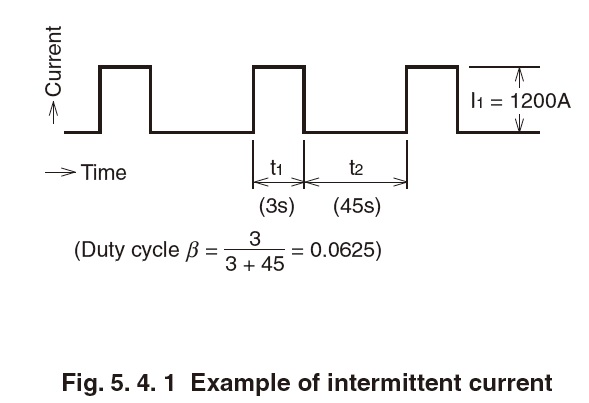
RMS value. The heating value in the energized state as shown in Fig. 5. 4. 1 can be obtained by the following formula.
W = I12Rt1, where R is the resistance.
The mean production heat can be obtained by the following formula.


This value is equal to the production heat obtained when current 

is continuously carried. The thermally equivalent current Ie in the example shown in Fig. 5. 4. 1 is


In this case, the continuous current of 300A and the average temperature are uniform, but the instantaneous temperature fluctuates as shown in Fig. 5. 4. 2, and the maximum temperature shown as Tm is higher than the average temperature Te at the continuous current of 300A. Operation of thermal MCCB is determined based on this maximum temperature. Therefore, it is necessary to select MCCB which will not operate at the maximum temperature, or to make sure that the operating time in the hot start mode is longer than the weld time. (For the hot start curve, see Appendix at the end of this book.) When selecting a magnetic-only MCCB, regard the thermally equivalent current as MCCB rated current. However, since MCCB rated current contains a margin of approx. 15% for supply voltage fluctuation and dispersion among devices, the rated current shall be just above 345A obtained by the following formula.


The operating time of electronic MCCB is shorter than that of thermal magnetic MCCB. To select the rated current of electronic MCCB, reduce the weld time t1 to 1/2 or less of the lower limit of the characteristic curve, and allow a margin of 40% for the thermally equivalent current.

 of lower limit of operating time at flowing current I1.

(2) Selection of MCCB based on welder capacity
In Item (1), MCCB is selected based on the welding conditions (working conditions). Since the welder working conditions are changed when the material to be welded is changed, you may think that MCCB must be changed every time the conditions are changed. However, if MCCB has been selected for the maximum working conditions allowable for the welder capacity and specifications in consideration of the operation limit of the welder, it is unnecessary to change MCCB in each case. According to JIS C9303 (Stationary type single phase AC spot welding machines), the rated capacities of welders are determined based on the duty cycle of 50%. When the rated capacity and rated voltage of the welder shown in Fig. 5. 3 are 85 kVA and 200V, the thermally equivalent continuous current Ie is:


MCCB rated current is just above the following value.

In this case, the relationship between the duty cycle b at which the operation limit is not exceeded and the maximum input Ibeta allowed at the duty cycle beta is:

Fig. 5.5 shows the graph of this relationship obtained by converting the duty cycle beta to the weld time with a cycle of 60 seconds. Accordingly, the thermally equivalent current of this welder is constantly 300A, but the operation limit varies depending on the duty cycle as shown below. At duty cycle of 50% (weld time of 30 sec): Input current of up to 425A At duty cycle of 6.25% (weld time of 3.75 sec): Input current of up to 1200A At duty cycle of 1% (weld time of 0.6 sec): Input current of up to 3000A However, since the primary input of welder is increased only by about 30% compared to the standard maximum welding current even if the secondary side is completely shortcircuited, when the standard maximum input of this welder is considered to be 400 kVA, the maximum primary input, Ibetamax, is:


Therefore, it is allowed to select MCCB for the maximum input Ibeta of 2600A or less. 
The 75% hot start characteristics of Model NF400-SW with rating of 350A are shown by the dashed line in Fig. 5. 5. The welder temperature rise characteristics to the upper limit are shown by the solid line in Fig. 5. 5. Although the allowable time vs. current curve for prevention of burnout of welder is above the solid line, it is necessary to examine whether or not MCCB can protect the welder in each case.

However, in most cases, magnetic-only MCCB are used for protection of thyristors and wire in case of short fault.


(3) Selection of instantaneous tripping current in consideration of transient magnetizing inrush current
When a transformer circuit is closed on the primary side, transient inrush current flows owing to superposition of DC and saturation of transformer core depending on the closing phase. Most of recent welders are provided with synchronous closing system and wave peak control or only with synchronous closing system for prevention of malfunction of protective devices due to the inrush current and for uniform welding conditions. In this case, the ratio of the RMS value of current in the steady state to the maximum peak value in the transient state is 

based on actual measurement. In the case of asynchronous closing with soft start, the ratio is 4 or less based on actual measurement.


The maximum instantaneous value of transient magnetizing inrush current in each case is shown below. 


If the synchronous closing system is used, the transient magnetizing inrush currents in both cases are almost identical. Therefore, for welders other than those of asynchronous closing type, it is allowed to regard Imax as 2Ibetamax. 

When the maximum primary input (Ibmax) is 2600A on a welder with synchronous closing system,

Since MCCB instantaneous tripping current is shown as the RMS value in the catalog, MCCB instantaneous tripping current (Iinst) can be obtained by the following formula.


Select MCCB whose Iinst is lower than the lower limit of instantaneous tripping current tolerances.

Selection of MCCB rated current for arc welder circuit
An arc welder is an intermittent load specified. MCCB rating can by selected by converting the load current into thermal equivalent continuous current. If this is taken as the rated current, however, the current duration per cycle will become relatively long, with the attendant danger of thermal tripping of MCCB. In the total period of 10 minutes, if the duty factor is 50%, a 141% overload exists for 5 minutes; if the duty factor is 40%, a 158% overload exists for 4 minutes; and if the duty factor is 20%, a 224% overload exists for 2 minutes. Thus:

The switching transient in the arc welder is measured as 8~9 times the primary current. Consequently, using 1.2 allowance, it is necessary to select instantaneous-trip characteristics such that MCCB does not trip with a current of 11 times the primary current.


Medium-Voltage Distribution System Design

A. Single Bus, Figure 1.1-40 The sources (utility and/or generator(s)) are connected to a single bus. All feeders are connected to the ...