Friday, 28 February 2020

Types of Systems


In many cases, power is supplied by the utility to a building at the utilization voltage. In these cases, the distribution of power within the building is achieved through the use of a simple radial distribution system.

Simple Radial System
In a conventional low-voltage radial system, the utility owns the pole-mounted or pad-mounted transformers that step their distribution voltage down from medium voltage to the utilization voltage, typically 480/277 Vac or 208/120 Vac. In these cases, the service equipment is generally a low-voltage main distribution switchgear or switchboard. Specific requirements for service entrance equipment may be found in NEC Article 230, Services. 

Low-voltage feeder circuits are run from the switchboard or switchgear assemblies to panelboards that are located closer to their respective loads as shown in Figure 1.1-24. Each feeder is connected to the switchgear or switchboard bus through a circuit breaker or other overcurrent protective device. A relatively small number of circuits are used to distribute power to the loads. Because the entire load is served from a single source, full advantage can be taken of the diversity among the loads. This makes it possible for the utility to minimize the installed transformer capacity. However, if capacity requirements grow, the voltage regulation and efficiency of this system may be poor because of the low-voltage feeders and single source. Typically, the cost of the low-voltage feeder circuits and their associated circuit breakers are high when the feeders are long and the peak demand is above 1000 kVA. 

Where a utility’s distribution system is fed by overhead cables, the likelihood of an outage due to a storm, such as a hurricane or blizzard, increases dramatically. Wind or ice formation can cause tree branches to fall on these suspended cables, causing an unplanned power outage. The failure of pole-mounted utility transformers canresult in an outage lasting a day or more. 

Additionally, a fault on the Service Switchgear or Switchboards low-voltage bus will cause the main overcurrent protective device to operate, interrupting service to all loads. Service cannot be restored until the necessary repairs have been made. A fault on a low-voltage feeder circuit will interrupt service to all the loads supplied by that feeder. 

An engineer needs to plan ahead for these contingencies by incorporating backup power plans during the initial design of the power system. Resiliency from storms, floods and other natural disasters can be accomplished with the addition of permanently installed standby generation, or by including a provision in the incoming Service equipment for the connection of a portable roll-up temporary generator.

Note: See Generator and Generator Systems in the Typical Power Systems Components section of this Design Guide for further details.

Figure 1.1-24. Low-Voltage Radial System


Figure 1.1-25 shows a typical incoming service switchboard with the addition of a key interlocked generator breaker. In this design, the breaker pair shares a single key that can only be used to close one breaker at a time. This arrangement ensures against paralleling with the utility but requires manual intervention in the event of an outage. 

In a typical standby generation arrangement, automatic transfer switches are used to feed either Normal utility power or an alternate generator source of backup power to the critical loads. The transfer switches sense the loss of power from the Normal source and send a run command to the generator to start.

Once the generator is running, the transfer switches sense that voltage is available and automatically open the Normal contactor and close the Generator contactor. When the Normal source returns, the transfer switch opens the Generator contactor and closes the Normal source contactor.

The location and type of the transfer switches depends on the Utility and the overall design intent. Transfer switches can be Service Entrance Rated and used as the main Service Disconnect feeding all the loads downstream. See Figure 1.1-26

Transfer switches can be also be incorporated into the service switchboard as an integral part of the assembly. 

Alternately, they can be located downstream of the incoming service and applied only to the individual loads they are feeding. This approach of isolating only those critical loads that must function during a power outage can reduce the generator kVA necessary. This can reduce space and cost requirements. 

It is important to consider the grounding of the generator neutral when using automatic transfer switches in power system design. If the generator neutral is grounded at the generator, a separately derived system is created. This requires the use of four-pole transfer switches for a three-phase system. 

If the three-phase generator neutral is brought back through the transfer switches and grounded at the service entrance, a three-pole transfer switch with solid neutral should be provided.

Figure 1.1-25. Typical Incoming Service Switchboard

Figure 1.1-26. Main Service Disconnect Feeding Downstream

In cases where the utility service voltage is at some voltage higher than the utilization voltage within the building, the system design engineer has a choice of a number of types of systems that may be used. This discussion covers several major types of distribution systems and practical modifications of them.
1. Simple medium-voltage radial
2. Loop-primary system radial secondary system
3. Primary selective system secondary radial system
4. Two-source primary— secondary selective system
5. Sparing transformer system
6. Simple spot network
7. Medium-voltage distribution system design

In those cases where the customer receives his supply from the primary system and owns the primary switch and transformer along with the secondary low-voltage switchboard or switchgear, the equipment may take the form of a separate primary switch, separate transformer, and separate low-voltage switchgear or switchboard. This equipment may be combined in the form of an outdoor pad-mounted transformer with internal primary fused switch and secondary main breaker feeding an indoor switchboard. 

Another alternative would be asecondary unit substation where the primary fused switch, transformer and secondary switchgear or switchboard are designed and installed as a closecoupled single assembly. 

A modern and improved form of the conventional simple medium voltage radial system distributes power at a primary voltage. The voltage is stepped down to utilization level in the several load areas within the building typically through secondary unit substation transformers. The transformers are usually connected to their associated load bus through a circuit breaker, as shown in Figure 1.1-28

Each secondary unit substation is an assembled unit consisting of a threephase, liquid-filled or air cooled transformer, an integrally connected primary fused switch, and low-voltage switchgear or switchboard with circuit breakers or fused switches. Circuits are run to the loads from these low-voltage protective devices. 

Because each transformer is located within a specific load area, it must have sufficient capacity to carry the peak load of that area. Consequently, if any diversity exists among the load area, this modified pimary radial system requires more transformer capacity than the basic form of the simple radial system. 

However, because power is distributed to the load areas at a primary voltage, losses are reduced, voltage regulation is improved, feeder circuit costs are reduced substantially, and large low-voltage feeder circuit breakers are eliminated. In many cases the interrupting duty imposed on the load circuit breakers is reduced. 

This modern form of the simple radial system will usually be lower in initial investment than most other types of primary distribution systems for buildings in which the peak load is above 1000 kVA. A fault on a primary feeder circuit or in one transformer will cause an outage to only those secondary loads served by that feeder or transformer. In the case of a primary main bus fault or a utility service outage, service is interrupted to all loads until the trouble is eliminated.

Figure 1.1-27. Simple Radial System


Figure 1.1-28. Primary and Secondary Simple Radial System

Reducing the number of transformers per primary feeder by adding more primary feeder circuits will improve the flexibility and service continuity of this system; the ultimate being one secondary unit substation per primary feeder circuit. This of course increases the investment in the system but minimizes the extent of an outage resulting from a transformer or primary feeder fault. 

Primary connections from one secondary unit substation to the next secondary unit substation can be made with “double” lugs on the unit substation primary switch as shown, or with load break or non-load break separable connectors made in manholes or other locations. See Eaton’s Cooper PowerE series Molded Rubber Medium Voltage Connectors on Eaton’s website for more details. 

Depending on the load kVA connected to each primary circuit and if no ground fault protection is desired for either the primary feeder conductors and transformers connected to that feeder or the main bus, the primary main and/or feeder breakers may be changed to primary fused switches. This will significantly reduce the first cost, but also decrease the level of conductor and equipment protection. Thus, should a fault or overload condition occur, downtime increases significantly and higher costs associated with increased damage levels and the need for fuse replacement is typically encountered. In addition, if only one primary fuse on a circuit opens, the secondary loads are then single phased, causing damage to low-voltage motors. 

Another approach to reducing costs is to eliminate the primary feeder breakers completely, and use a single primary main breaker or fused switch for protection of a single primary feeder circuit with all secondary unit substations supplied from this circuit. Although this system results in less initial equipment cost, system reliability is reduced drastically because a single fault in any part of the primary conductor would cause an outage to all loads within the facility.
Wednesday, 26 February 2020

Low-Voltage Utilization


With most low-voltage services, the service voltage is the same as the utilization voltage. However, when the engineer is faced with a decision between 208Y/120 V and 480Y/277 V secondary distribution for commercial and institutional buildings, the choice depends on several factors. The most important of these are the size and types of loads (motors, fluorescent lighting, incandescent lighting, receptacles) and length of feeders. In general, power system designs with HVAC equipment with a significant quantity of motors, predominantly fluorescent lighting loads, and long feeders, will tend to make 480Y/277 V more economical. 

Industrial installations with large motor loads are almost always 480 V resistance grounded, wye systems (see further discussion on this topic in the Grounding/ Ground Fault Protection section of this Design Guide). 

Practical Factors
Because most low-voltage distribution equipment available is rated for up to 600 V, and conductors are insulated for 600 V, the installation of 480 V systems uses the same techniques and is essentially no more difficult, costly or hazardous than for 208 V systems. The major difference is that an arc of 120 V to ground tends to be self-extinguishing, while an arc of 277 V to ground tends to be self-sustaining and likely to cause severe damage. 

For this reason, Article 230.95 of the National Electrical Code requires ground fault protection of equipment on grounded wye services of more than 150 V to ground, but not exceeding 600 V phase to-phase (for practical purpose, 480Y/277 V services), for any service disconnecting means rated 1000 A or more. 

Article 215.10 of the NEC extends this equipment ground fault requirement to feeder conductors and clarifies the need for equipment ground fault protection for 1000 A and above, feeder circuit protective devices on the 480/277 Vac secondary of transformers. Article 210.13 has been added to the 2014 NEC, essentially recognizing the same need for equipment ground fault protection on 1000 A branch circuits being fed from the 480/277 Vac secondary of transformers. 

The National Electrical Code permits voltage up to 300 V to ground on circuits supplying permanently installed electric discharge lamp fixtures, provided the luminaires do not have an integral manual switch and are mounted at least 8 ft (2.4 m) above the floor. This permits a three-phase, four-wire, solidly grounded 480Y/277 V system to supply directly all of the fluorescent and high-intensity discharge (HID) lighting in a building at 277 V, as well as motors at 480 V.

Technical Factors
The principal advantage of the use of higher secondary voltages in buildings is that for a given load, less current means smaller conductors and lower voltage drop. Also, a given conductor size can supply a large load at the same voltage drop in volts, but a lower percentage voltage drop because of the higher supply voltage. Fewer or smaller circuits can be used to transmit the power from the service entrance point to the final distribution points. Smaller conductors can be used in many branch circuits supplying power loads, and a reduction in the number of lighting branch circuits is usually possible. 

It is easier to keep voltage drops within acceptable limits on 480 V circuits than on 208 V circuits. When 120 V loads are supplied from a 480 V system through step-down transformers, voltage drop in the 480 V supply conductors can be compensated for by the tap adjustments on the transformer, resulting in full 120 V output. Because these transformers are usually located close to the 120 V loads, secondary voltage drop should not be a problem. If it is, taps may be used to compensate by raising the voltage at the transformer. 

The interrupting ratings of circuit breakers and fuses at 480 V have increased considerably in recent years, and protective devices are now available for any required fault duty at 480 V. In addition, many of these protective devices are current limiting, and can be used to protect downstream equipment against these high fault currents.


Economic Factors
Utilization equipment suitable for principal loads in most buildings is available for either 480 V or 208 V systems. Three-phase motors and their controls can be obtained for either voltage, and for a given horsepower are less costly at 480 V. LED lighting as well as earlier technologies including fluorescent, HID and high pressure sodium can all be applied in either 480 V or 208 V systems. However, in almost all cases, the installed equipment will have a lower total cost at the higher voltage.

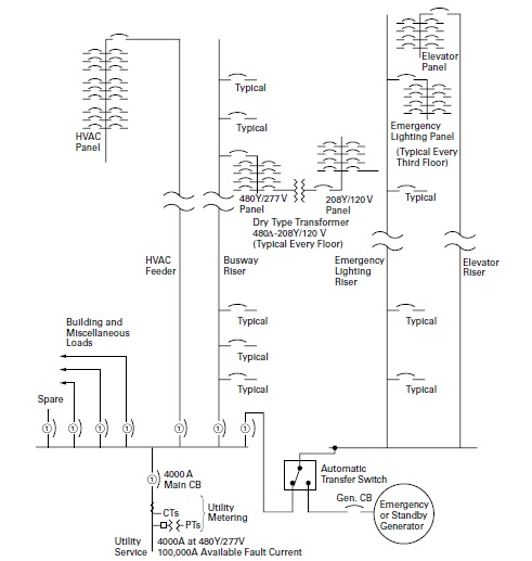
Figure 1.1-23. Typical Power Distribution and Riser Diagram for a Commercial Office Building

Utilization Voltage Selection


Very large inductive loads such as higher horsepower motors used on HVAC chillers, sewage treatment pumps and in process or other Industries can draw tremendous amounts of power. Motors also inherently have high inrush currents during full voltage starting, which can cause a significant voltage dip on the power system feeding it. As a result, many utilities have limitations on the maximum horsepower motor that can be line started directly from their system. To limit the impact of this phenomena, a variety of techniques can be used to reduce the motor’s starting inrush current. These generally involve the use of electromechanical or solid state reduced voltage starters. Variable frequency drives in both low and medium voltage are also available as shown on the System One-Line on Page 1.1-8. See Components of a Power System section for further details.

Voltage Recommendations by Motor Horsepower
Some factors affecting the selection of motor operating voltage include:
■■ Motor, motor starter and cable first cost
■■ Motor, motor starter and cable installation cost
■■ Motor and cable losses
■■ Motor availability
■■ Voltage drop
■■ Qualifications of the building operating staff; and many more
The following table is based in part on the above factors and experience. Because all the factors affecting the selection are rarely known, it is only an approximate guideline.


Table 1.1-5. Selection of Motor Horsepower Ratings as a Function of System Voltage


In higher motor hp applications, a motor’s 4.16 kV utilization voltage may be the same as the 4.16 kV service voltage. In these cases, the service equipment would need to feed power through cables or busway to a medium-voltage starter or variable frequency drive. However, in installations where there are many long cable runs that are feeding other large loads, the medium-voltage distribution may have a higher service voltage such as 13.8 kV. In this case, the service voltage would need to be stepped-down to the 4.16 kV utilization voltage through a primary unit substation transformer as illustrated by the System One-Line on Page 1.1-8. Conversely, small end loads, short runs and a high percentage of lighting and/or receptacle loads would favor lower utilization voltages such as 208 Y/120 V. If the incoming service was at 13.8 kV, as noted in the previous example, secondary unit substations, pad-mounted transformers or unitized power centers could be used to step down to the 208 Y/120 V utilization voltage required. This approach is often used to reduce or offset voltage drop issues on multi building sites such as college or hospital campuses. It is also used in large single building sites like distribution warehouses and high rise “skyscraper” buildings.
Note: The “Types of Systems” section of this Design Guide illustrates a number of power system designs that improve reliability and uptime during maintenance or service outages. Among these schemes are a variety of configurations showing medium-voltage sources feeding substation or pad-mounted transformers that step it down to the appropriate low voltage for end load utilization.
A problem can arise, however, when a low-voltage service is the only utility service option and cable distances between the incoming service and the utilization loads are great. In these instances, a practical way to offset for the voltage drop to the end utilization loads is the use of low-voltage busway in lieu of cable. Another technique to address voltage drop concerns for long cable runs is to use a step-up and step down transformer arrangement.  To accomplish this, a step-up transformer is added after the low-voltage service. The transformer primary is configured in a delta and is fed by the grounded and bonded low-voltage incoming utility service. The step-up transformer wye secondary is often at medium voltage, typically at 4.16 kV, with the transformers wye secondary grounded. A 4.16 kV delta primary step-down transformer is then located near the served load and has its wye secondary grounded in accordance with NEC Article 250.30 to create a separately derived system. This step-down transformer’s secondary voltage may be the same as the incoming service, or it may be at higher utilization voltage. Caution must be taken when selecting the step-up transformers to be used in this type of application. Step-up transformers, particularly designs that are not optimized for step-up purposes, such as a reverse-fed standard transformer, exhibit extremely high inrush during energization. Unless the step-up transformers are specifically wound for low inrush, the magnetizing current during initial energization, may exceed the 6X make capabilities of a low-voltage fused bolted pressure switch. This can result in a condition where a portion of the switch contact surface can weld before full engagement. The current passing through the smaller contact area will then eventually cause the switch to overheat and fail. Many step-up transformer applications involve a 208 Vac incoming service stepping this voltage up to the utilization voltage of 480 Vac for HVAC motor loads in a building. The design engineer must be aware of some potential pitfalls and plan ahead when involved in this type of application. Larger step-up transformers offer fewer transformer voltage taps, if any at all. They also exhibit poor voltage regulation when experiencing transient shock loads, such as motors starting. When designing power systems utilizing step up transformers to feed motor loads, a Motor Starting Analysis should be performed to ensure that the motors will start and operate as intended.

To be continued...

Tuesday, 25 February 2020

Incoming Service Considerations


Article 230 of the National Electrical Code: “covers service conductors and equipment for the protection of services and their installation requirements”. Figure 1.1-22 provides the scope of pertinent references that apply to incoming service equipment. These range from conductor types from overhead service utility drops to underground utility feeds and their proper installation. 

Parts V, VI and VII of Article 230 spell out the common requirements for lowvoltage service equipment <1000 Vac. These parts cover locations permitted, various marking requirements including Section 230.66 that requires service equipment be listed and marked as Suitable for Use as Service Equipment, (SUSE). Also included is Section 230.71, which limits the number of incoming main service disconnects to a maximum of six. 

Section 230.95 of this Article requires equipment ground fault protection for service disconnect(s) 1000 A and above when applied on solidly grounded wye services, where the phase to ground voltage exceeds 150 V. 

Article 250 of the NEC contains the requirements for grounding and bonding of electrical systems. Specific details pertaining to grounding for the incoming service equipment begin at Section 250.24. 

These include application of the grounding electrode conductor in Section 250.50 to its sizing in accordance with Table 250.66. Requirements for bonding of service equipment begins in Section 250.90. Sizing of the main bonding jumper and system bonding jumper are also covered in Table 250.102(C)(1). 

A more in-depth discussion of ground fault protection can be found in Section 1.5 of this Design Guide.


Figure 1.1-22. Application Zones of 2014 NEC Articles Related to Incoming Utility Services

The NEC Article 230 does not specifically require that electrical service rooms be fire rated rooms or that sprinklers be provided. However, survivability requirements for fire pump disconnects in local building code requirements, in addition to NEC Article 450 or additional utility specifications may require fire rated rooms, particularly if mediumvoltage service is being supplied. 

Space allocation should be considered when laying out equipment in a service room. Both low- and medium-voltage utility metering typically adds an additional equipment structure, or structures, to an incoming service lineup. These are used to accommodate the current transformers and potential taps or voltage transformers necessary for the external utility revenue meter to calculate usage.

Article 110 of the NEC covers a broad range of requirements for electrical installations. It includes provisions that govern the construction and spatial requirements for egress, clearances and working space in rooms containing electrical distribution and service equipment. 

Table 1.1 4 includes combined tables from NEC Article 110, showing the minimum “depth of the working space in the direction of live parts” required in front and behind medium-voltage equipment and low-voltage equipment.

Table 1.1-4. NEC Minimum Depth of Clear Working Space at Equipment
Additional work space may need to be allocated for OSHA required grounding practices, prior to servicing deenergized medium-voltage equipment. As an example, 6-foot-long insulated hot sticks are typically used to keep personnel at a safe distance, while applying portable ground cables. This procedure is utilized to discharge any residual capacitive voltage present on cables terminating in a medium-voltage transformer primary cable compartment or in the rear cable compartment of medium voltage switchgear.


As renewable energy or cogeneration is added, power systems are becoming more complex and so too is their service interface for utility power. Many Public Service Commissions have adopted Standard Interface Requirements (SIR) for Distributed Energy Resources (DER) based on IEEE 1547. These are intended to protect the utility system from user owned generation back feeding into a fault or dead cable on the utility grid. 

Utilities may have their own specifications and tariffs for the interconnection of this Dispersed or Distributed Generation (DG). These include capacity limitations and/or the addition of charges for the “spinning reserves” they must keep on hand, should the user’s DG assets fail or load increase. 

Consequently, the design engineer must be aware that special relaying protection may need to be included in the design. Also, additional analysis of the utility tariffs and rate structures may be necessary to validate the projected payback of participation in peak demand reduction programs using owner-supplied generation.


Monday, 24 February 2020

Power System Voltages


The System One-Line on Part-1, shows an Incoming utility primary service feeding different types of distribution equipment at each of the various utilization voltages necessary to power the actual loads. 

The One-Line illustrates a number of voltage transformations and is a good example of the types of choices and challenges a power systems design engineer faces today.

Voltage Classifications
ANSI and IEEET standards define various voltage classifications for single-phase and three phase systems. The terminology used divides voltage classes into:
■■ Low voltage
■■ Medium voltage
■■ High voltage
■■ Extra-high voltage
■■ Ultra-high voltage
Table 1.1-3 presents the nominal system voltages for these classifications.

Table 1.1-3. Standard Nominal System Voltages and Voltage Ranges (From IEEE Standard 141-1993)
The 2014 National Electrical Code has ushered in a change to the definition of low voltage. The NEC elevated the maximum voltage threshold for this category from 600 V maximum to 1000 V maximum. This was done to accommodate the growing solar market where voltages up to 1000 V are becoming more commonplace. 

In general, the voltage classes above medium voltage are utilized for transmission of bulk power from generating stations to the utilities substations that transform it to the distribution voltage used on their system.

A power system design engineer should attempt to familiarize themselves with the application of all equipment available in the various voltage classes. This is particularly true if they are involved in designing industrial facilities or campus arrangements that may be served by a utility at medium or high voltage.

Incoming Service Voltage
When designing a new power distribution system, the engineer needs to be knowledgeable of the local utility requirements including the service voltage that is available to be provided for their client. Meeting with the utility’s customer service representative responsible for the installation site, early in the design process, can help set expectations for both parties and avoid subsequent delays.

Most utilities will require a load letter when requesting a new service or upgrade to an existing utility service. The letter must include calculated values for the types of continuous and noncontinuous loads that will be served.

Article 220 of the NEC covers branchcircuit, feeder and service calculations. It also includes references to other articles that pertain to specific types of installations requiring special calculation considerations. 

The determination of the utility service voltage is driven by a combination of factors including the engineers initial load letter, prevailing utility standards and the type of facility being served. 

Excessively high megawatt loads such as those required by large wastewater treatment plants or complex process facilities like petrochemical refining will typically exceed the utility’s infrastructure to serve the end customer at low-voltage. In these instances, a medium voltage service at 34.5, 33 kV, 26.4 kV, 13.8 kV, 13.2 kV, 12.47 kV or 4.16 kV will be mandated. Extremely large loads may even involve a utility interconnect at the 69 kV or high voltage level. 

The System One-Line on Part-1 is an example of a power system for a hypothetical college campus with a design load over 8 megawatts at a 0.8 power factor. This would require a Utility service of over 400 A at 13.8 kV. 

The most common service voltage arrangements are in the low-voltage range (<600 Vac). Normal residential services are at 240/120 three-wire, (two phases each at 240 and a Neutral Conductor). Connection from each 240 V phase to neutral provides 120 V for the lighting and plug loads.

A three-phase, four-wire low-voltage service is generally provided for commercial customers. It includes a neutral and may be provided at 208/120 Vac wye, 240/120 Vac wye or 480 /277 Vac wye. 

Typical applications for the commercial category of three-phase low-voltage services are small commercial buildings, department stores, office buildings, kindergarten through 12th grade schools and light manufacturing facilities. 

There are a number of other older service configurations utilized in rural locations such as Delta Hi Leg. These were used as an inexpensive way to supply 240 V three-phase and 240 V or 120 V single-phase from a single pole mount transformer. 

As a general rule, the serving utility will offer a basic service option that is outlined in the tariff documents that have been approved by the governing authority or agency that regulates the utility. This basic service option is one that minimizes the utility costs and best accommodates their system requirements. 

The utility may alternately offer to upcharge the client for extending or reinforcing cable connections to a location on their overhead or underground grid where they can supply the service the user is requesting. In major cities where the serving utility utilizes underground spot networks, the option to select a voltage other than that available is either limited or extremely expensive. 

Utility metering requirements vary from one serving entity to another and are more complex for medium-voltage switchgear used as service equipment. 

Commercial low-voltage utility metering (<600 V) is more common and includes standardized designs that can be provided in various lowvoltage switchboard and drawout switchgear configurations.

Sunday, 23 February 2020

Designing of Distribution System (Part - 6) - Additional Drawings, Schedules and Specifications


Additional Drawings, Schedules and Specifications
While a Power System One-Line is the basis for defining the interrelationships between the various types of distribution equipment, there is often more information that needs to be conveyed. 

Because the end loads and the conductors feeding them are the basis for proper selection and application of the circuit breakers, a valuable step in the selection process is developing a schedule. 

The overcurrent protection of many loads, such as motors and distribution transformers, must conform to the requirements of Articles 240, 430 and 450 of the National Electrical Code. Particular consideration needs to be given to the length and type of conductors that will need to connect the distribution equipment. 

As cable length increases, so does its resistance in the circuit leading to a drop in the voltage at the end of the conductor run feeding the loads. Cable lengths exceeding 100 feet generally need to be upsized to offset for voltage drop concerns. 

Cable length, size and the raceway they are installed in, also have an impact on the impedance of the conductor in the circuit. Greater impedance helps to reduce the available short circuit at the terminals of the distribution equipment or end load.

The 310.15(B) (3) from the National Electrical Code defines the Allowable Ampacities of Insulated Conductors rated 0-90 degrees C. While details of this table are included in the reference section of this chapter, it should be noted that Listed Distribution Equipment is provided with terminations rated at 75 °C. 

From a pragmatic standpoint, this means that the equipment could be fed from conductors rated at either 60 °C or 75 °C. Derating would be required for the conductor ampacity at 60 °C making it less practical. It also means that the equipment could be fed from 90 °C conductors, but only if applied at the 75 °C ratings due to the limitations of the equipment ratings. 

The following tables are adjusted in accordance with NEC 240.4(D) to show the actual allowable ampacities of copper and aluminum conductors terminating in electrical distribution assemblies. 

A schedule based on the allowable ampacity of copper conductors in Table 1.1-1 is shown in Figure 1.1-19. It includes the relevant requirements for secondary unit substation “SUS-F1A” shown on the One-Line. This schedule outlines the breaker frame sizes, trip settings and particulars of the trip units required.

It also annotates the names for the breakers as well as their circuit nameplate designations. The cable sizes and quantities are determined by utilizing the tables in the NEC, (as condensed into Table 1.1-1).

The equipment ground sizes are per NEC Table 250.122 based on the trip rating of the overcurrent device protecting the phase and neutral conductors. Note that they do not take voltage drop into consideration.


Table 1.1-1. Ampacity of CU Conductors

 
Table 1.1-2. Ampacity of AL Conductors


Figure 1.1-19. Unit Substation Cable Entry Position


In order to provide an effective ground fault path as required by 250.4(A)(5) and 250.4(B)(4) of the 2014 NEC, upsizing of the equipment ground conductors are required by Article 250.122(B) “when the ungrounded conductors are increased in size from the minimum size that has a sufficient ampacity for the intended installation”. 

In these cases, “wire-type equipment grounding conductors, where installed, shall be increased in size proportionally according to the circular mil area of the ungrounded conductors”. 

When developing schedules, it is important to remember that conductor sizing is also impacted by the derating tables for ambient temperature and conductor fill when installed in raceways. 

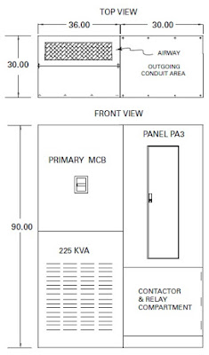
There are a number of ways to create cable schedules, the most common of which is to name the conductor as is shown on the medium voltage portion of the One-Line in Figure 1.1-2. Schedules are most often used to define requirements for low-voltage switchboards and panelboards. They may also be utilized to enumerate the various automatic transfer switches and the cables connecting them to the normal and emergency sources as well as the end load. Other drawings that are necessary to produce the installation package are floor plans that include room dimensions, equipment locations allocated within the space, appropriate clearances per code requirements and means of egress from the area where the equipment is located. These drawings have been done primarily in 2D CAD programs with boxes showing equipment dimensions on the floorplan. A front view of the equipment is also used to detail the elevation requirements. Equipment occasionally requires top hats or pullboxes that add height above the switchboard or switchgear. On other occasions, the room does not have enough height to accommodate standard equipment. In these cases, special reduced height switchboards or switchgear may be provided. While this equipment may not be documented as standard, Eaton can provide assistance in developing a reduced height alternative solution.
As design and drafting tools have evolved, the push to include 3D drawings has subsequently evolved into an enhanced technology called Building Information Modeling (BIM). BIM drawings include the 3D aspect but also include the capability to assign equipment performance parameters and interdependencies. This permits architects and construction firms to be alerted to potential “collisions” between incoming/ outgoing conduits and other potential obstructions such as existing conduits/ busduct, HVAC duct or plumbing in the space above or below the equipment.


Figure 1.1-20. Equipment Floorplan and Elevation


Figure 1.1-21. BIM 3D Model Top View

Medium-Voltage Distribution System Design

A. Single Bus, Figure 1.1-40 The sources (utility and/or generator(s)) are connected to a single bus. All feeders are connected to the ...