Additional
Drawings, Schedules and Specifications
While a Power System One-Line is the basis for defining the
interrelationships between the various types of distribution equipment, there
is often more information that needs to be conveyed.
Because the end loads and
the conductors feeding them are the basis for proper selection and application
of the circuit breakers, a valuable step in the selection process is developing
a schedule.
The overcurrent protection of many loads, such as motors and distribution
transformers, must conform to the requirements of Articles 240, 430 and 450 of
the National Electrical Code. Particular consideration needs to be given to the
length and type of conductors that will need to connect the distribution
equipment.
As cable length increases, so does its resistance in the circuit
leading to a drop in the voltage at the end of the conductor run feeding the
loads. Cable lengths exceeding 100 feet generally need to be upsized to offset
for voltage drop concerns.
Cable length, size and the raceway they are
installed in, also have an impact on the impedance of the conductor in the circuit.
Greater impedance helps to reduce the available short circuit at the terminals
of the distribution equipment or end load.
The 310.15(B) (3) from the National Electrical Code defines the
Allowable Ampacities of Insulated Conductors rated 0-90 degrees C. While
details of this table are included in the reference section of this chapter, it
should be noted that Listed Distribution Equipment is provided with terminations
rated at 75 °C.
From a pragmatic standpoint, this means that the equipment
could be fed from conductors rated at either 60 °C or 75 °C. Derating would be required
for the conductor ampacity at 60 °C making it less practical. It also means
that the equipment could be fed from 90 °C conductors, but only if applied at
the 75 °C ratings due to the limitations of the equipment ratings.
The
following tables are adjusted in accordance with NEC 240.4(D) to show the
actual allowable ampacities of copper and aluminum conductors terminating in electrical
distribution assemblies.
A schedule based on the allowable ampacity of copper
conductors in Table 1.1-1 is
shown in Figure 1.1-19.
It includes the relevant requirements for secondary unit substation “SUS-F1A” shown
on the One-Line. This schedule outlines the breaker frame sizes, trip settings
and particulars of the trip units required.
It also annotates the names for the
breakers as well as their circuit nameplate designations. The cable sizes and
quantities are determined by utilizing the tables in the NEC, (as condensed
into Table 1.1-1).
The
equipment ground sizes are per NEC Table 250.122 based on the trip rating of the
overcurrent device protecting the phase and neutral conductors. Note that they
do not take voltage drop into consideration.
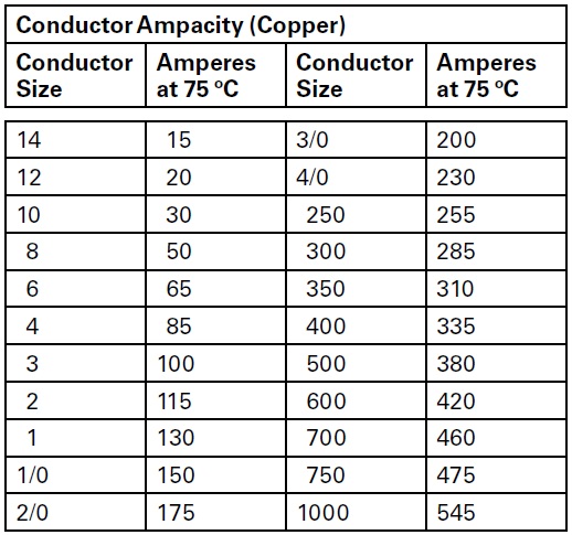 |
| Table 1.1-1. Ampacity of CU Conductors |
 |
Table 1.1-2. Ampacity of AL Conductors
 |
Figure 1.1-19. Unit Substation Cable Entry Position
In
order to provide an effective ground fault path as required by 250.4(A)(5) and
250.4(B)(4) of the 2014 NEC, upsizing of the equipment ground conductors are
required by Article 250.122(B) “when the ungrounded conductors are increased in
size from the minimum size that has a sufficient ampacity for the intended
installation”.
In these cases, “wire-type equipment grounding conductors, where
installed, shall be increased in size proportionally according to the circular
mil area of the ungrounded conductors”.
When developing schedules, it is
important to remember that conductor sizing is also impacted by the derating
tables for ambient temperature and conductor fill when installed in raceways.
There
are a number of ways to create cable schedules, the most common of which is to
name the conductor as is shown on the medium voltage portion of the One-Line in
Figure 1.1-2. Schedules are most often used to define requirements for
low-voltage switchboards and panelboards. They may also be utilized to enumerate
the various automatic transfer switches and the cables connecting them to the
normal and emergency sources as well as the end load. Other drawings that are
necessary to produce the installation package are floor plans that include room
dimensions, equipment locations allocated within the space, appropriate
clearances per code requirements and means of egress from the area where the
equipment is located. These drawings have been done primarily in 2D CAD programs
with boxes showing equipment dimensions on the floorplan. A front view of the equipment
is also used to detail the elevation requirements. Equipment occasionally
requires top hats or pullboxes that add height above the switchboard or
switchgear. On other occasions, the room does not have enough height to
accommodate standard equipment. In these cases, special reduced height
switchboards or switchgear may be provided. While this equipment may not be documented
as standard, Eaton can provide assistance in developing a reduced height
alternative solution.
As
design and drafting tools have evolved, the push to include 3D drawings has
subsequently evolved into an enhanced technology called Building Information
Modeling (BIM). BIM drawings include the 3D aspect but also include the capability
to assign equipment performance parameters and interdependencies. This permits
architects and construction firms to be alerted to potential “collisions”
between incoming/ outgoing conduits and other potential obstructions such as
existing conduits/ busduct, HVAC duct or plumbing in the space above or below
the equipment.
 |
Figure 1.1-20. Equipment Floorplan and Elevation
 |
Figure 1.1-21. BIM 3D Model Top View


No comments:
Post a Comment